- Electric
motor, a machine that converts electricity into a mechanical
motion
- Thermodynamic
motor or engine, a machine that converts heat into mechanical
motion
- Molecular
motors, the essential agents of movement in living organisms
- Pneumatic
motor, a machine that converts the energy of compressed
air into mechanical motion
- Hydraulic
motor a machine that converts the energy of pressurized
liquid flow into mechanical motion.
- Synthetic
molecular motors or nanomotors
Motor
may also refer to:
- Motor
car or automobile
- Motor
vehicle
- Motor
system, the physiological system that is responsible for
physical movement
- Motor
neuron, neurons that originate in the spinal cord and synapse
with muscle fibers
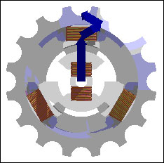
Rotating
magnetic field as a sum of magnetic vectors from 3 phase coils.
An electric
motor converts electrical energy into kinetic energy. The
reverse task, that of converting kinetic energy into electrical
energy, is accomplished by a generator or dynamo. In many
cases the two devices differ only in their application and
minor construction details, and some applications use a single
device to fill both roles. For example, traction motors used
on locomotives often perform both tasks if the locomotive
is equipped with dynamic brakes.
Operation
Most electric
motors work by electromagnetism, but motors based on other
electromechanical phenomena, such as electrostatic forces
and the piezoelectric effect, also exist. The fundamental
principle upon which electromagnetic motors are based is that
there is a mechanical force on any current-carrying wire contained
within a magnetic field. The force is described by the Lorentz
force law and is perpendicular to both the wire and the magnetic
field. Most magnetic motors are rotary, but linear motors
also exist. In a rotary motor, the rotating part (usually
on the inside) is called the rotor, and the stationary part
is called the stator. The rotor rotates because the wires
and magnetic field are arranged so that a torque is developed
about the rotor's axis. The motor contains electromagnets
that are wound on a frame. Though this frame is often called
the armature, that term is often erroneously applied. Correctly,
the armature is that part of the motor across which the input
voltage is supplied. Depending upon the design of the machine,
either the rotor or the stator can serve as the armature.
DC
motors
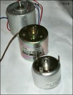 Electric
motors of various sizes. Electric
motors of various sizes.
One of
the first electromagnetic rotary motors was invented by Michael
Faraday in 1821 and consisted of a free-hanging wire dipping
into a pool of mercury. A permanent magnet was placed in the
middle of the pool of mercury. When a current was passed through
the wire, the wire rotated around the magnet, showing that
the current gave rise to a circular magnetic field around
the wire. This motor is often demonstrated in school physics
classes, but brine(salt water) is sometimes used in place
of the toxic mercury. This is the simplest form of a class
of electric motors called homopolar motors. A later refinement
is the Barlow's Wheel.
Another
early electric motor design used a reciprocating plunger inside
a switched solenoid; conceptually it could be viewed as an
electromagnetic version of a two stroke internal combustion
engine.
The modern
DC motor was invented by accident in 1873, when Zénobe
Gramme connected a spinning dynamo to a second similar unit,
driving it as a motor.
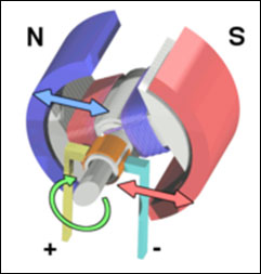
The classic
DC motor has a rotating armature in the form of an electromagnet.
A rotary switch called a commutator reverses the direction
of the electric current twice every cycle, to flow through
the armature so that the poles of the electromagnet push and
pull against the permanent magnets on the outside of the motor.
As the poles of the armature electromagnet pass the poles
of the permanent magnets, the commutator reverses the polarity
of the armature electromagnet. During that instant of switching
polarity, inertia keeps the classical motor going in the proper
direction. (See the diagrams below.)
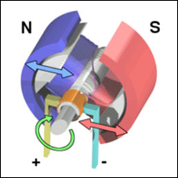
A simple
DC electric motor. When the coil is powered, a magnetic field
is generated around the armature. The left side of the armature
is pushed away from the left magnet and drawn toward the right,
causing rotation.
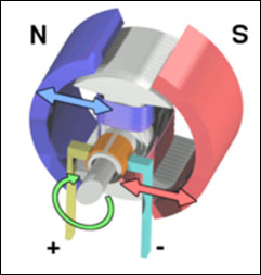
The
armature continues to rotate.
When
the armature becomes horizontally aligned, the commutator
reverses the direction of current through the coil, reversing
the magnetic field. The process then repeats.
Wound
field DC motor
The permanent
magnets on the outside (stator) of a DC motor may be replaced
by electromagnets. By varying the field current it is possible
to alter the speed/torque ratio of the motor. Typically the
field winding will be placed in series (series wound) with
the armature winding to get a high torque low speed motor,
in parallel (shunt wound) with the armature to get a high
speed low torque motor, or to have a winding partly in parallel,
and partly in series (compound wound) for a balance that gives
steady speed over a range of loads. Further reductions in
field current are possible to gain even higher speed but correspondingly
lower torque, called "weak field" operation.
Theory
If the
shaft of a DC motor is turned by an external force, the motor
will act like a generator and produce an electric motive force
(EMF). This voltage is also generated during normal motor
operation. The spinning of the motor produces a voltage known
as the back EMF because it opposes the applied voltage on
the motor. Therefore the voltage drop across a motor consists
of the voltage drop due to this back EMF and the parasitic
voltage drop resulting from the internal resistance of the
apperature's windings. The current through a motor is given
by the following equation:
I = (Vapplied
? Vbackemf) / Rapperature-
The mechanical power produced by the motor is given by:
P = I * Vbackemf-
Since
the back EMF is proportional to motor speed, when an electric
motor is first started or is completely stalled, there is
zero back EMF. Therefore the current through the apperature
is much higher. This high current will produce a strong electric
field which will start the motor spinning. As the motor spins,
the back EMF increases until it is equal to the applied voltage
minus the parasitic voltage drop. At this point there will
be a smaller current flowing through the motor. Basically
the following three equations can be used to find the speed,
current, and back EMF of a motor under a load:
Load =
Vbackemf * I-
Vapplied = I * Rapperature ? Vbackemf-
Vbackemf = speed * Fluxapperature-
Speed
control
Generally,
the rotational speed of a DC motor is proportional to the
voltage applied to it, and the torque is proportional to the
current. Speed control can be achieved by variable battery
tappings, variable supply voltage, resistors or electronic
controls. The direction of a wound field DC motor can be changed
by reversing either the field or armature connections but
not both. This is commonly done with a special set of contactors
(direction contactors).
The effective voltage can be varied by inserting a series
resistor or by an electronically controlled switching device
made of thyristors, transistors, or, formerly, mercury arc
rectifiers. In a circuit known as a chopper, the average voltage
applied to the motor is varied by switching the supply voltage
very rapidly. As the "on" to "off" ratio
(duty cycle) is varied to alter the average applied voltage,
the speed of the motor varies. The percentage "on"
time multiplied by the supply voltage gives the average voltage
applied to the motor. Therefore, with a 100 V supply and a
25% "on" time the average voltage at the motor will
be 25 V. During the "off" time, current in the motor
flows through a diode called a "flywheel diode".
At this point in the cycle the supply current will be zero,
and therefore the average motor current will always be higher
than the supply current unless the percentage "on"
time is 100%. At 100% "on" time the supply and motor
current are equal. The rapid switching wastes less energy
than series resistors. Output filters smooth the average voltage
applied to the motor and reduce motor noise. This method is
also called pulse width modulation, or PWM, and is often controlled
by a microprocessor.
Since the series-wound DC motor develops its highest torque
at low speed, it is often used in traction applications such
as electric locomotives, and trams. Another application is
starter motors for petrol and small diesel engines. Series
motors must never be used in applications where the drive
can fail (such as belt drives). As the motor accelerates,
the armature (and hence field) current reduces. The reduction
in field causes the motor to speed up (see 'weak field' in
the last section) until it destroys itself. This can also
be a problem with railway motors in the event of a loss of
adhesion since, unless quickly brought under control, the
motors can reach speeds far higher than they would do under
normal circumstances. This can not only cause problems for
the motors themselves and the gears, but due to the differential
speed between the rails and the wheels it can also cause serious
damage to the rails and wheel treads as they heat and cool
rapidly. Field weakening is used in some electronic controls
to increase the top speed of an electric vehicle. The simplest
form uses a contactor and field weakening resistor, the electronic
control monitors the motor current and switches the field
weakening resistor in circuit when the motor current reduces
below a preset value (this will be when the motor is at its
full design speed). Once the resistor is in circuit the motor
will increase speed above its normal speed at its rated voltage.
When motor current increases the control will disconnect the
resistor and low speed torque is made available.
One interesting method of speed control of a DC motor is the
Ward Leonard control. It is a method of controlling a DC motor
(usually a shunt or compound wound) and was developed as a
method of providing a speed-controlled motor from an AC supply,
though it is not without its advantages in DC schemes. The
AC supply is used to drive an AC motor, usually an induction
motor that drives a DC generator or dynamo. The DC output
from the armature is directly connected to the armature of
the DC motor (usually of identical construction). The shunt
field windings of both DC machines are excited through a variable
resistor from the generator's armature. This variable resistor
provides extremely good speed control from standstill to full
speed, and consistent torque. This method of control was the
de facto method from its development until it was superseded
by solid state thyristor systems. It found service in almost
any environment where good speed control was required, from
passenger lifts through to large mine pit head winding gear
and even industrial process machinery and electric cranes.
Its principal disadvantage was that three machines were required
to implement a scheme (five in very large installations, as
the DC machines were often duplicated and controlled by a
tandem variable resistor). In many applications, the motor-generator
set was often left permanently running to avoid the delays
that would otherwise be caused by starting it up as required.
There are numerous legacy Ward-Leonard installations still
in service.
Universal
motors
A variant
of the wound field DC motor is the universal motor. The name
derives from the fact that it may use AC or DC supply current,
although in practice they are nearly always used with AC supplies.
The principle is that in a wound field DC motor the current
in both the field and the armature (and hence the resultant
magnetic fields) will alternate (reverse polarity) at the
same time, and hence the mechanical force generated is always
in the same direction. In practice the motor must be specially
designed to cope with the AC current (impedance must be taken
into account as must the pulsating force), and the resultant
motor is generally less efficient than an equivalent pure
DC motor. Operating at normal power line frequencies, the
maximum output of universal motors is limited and motors exceeding
one kilowatt are rare. But universal motors also form the
basis of the traditional railway traction motor. In this application,
to keep their electrical efficiency high, they were operated
from very low frequency AC supplies with 25 Hz and 16 2/3
hertz operation being common. Because they are universal motors,
locomotives using this design were also commonly capable of
operating from a third rail powered by DC.
The advantage of the universal motor is that AC supplies may
be used on motors which have the typical characteristics of
DC motors, specifically high starting torque and very compact
design if high running speeds are used. The negative aspect
is the maintenance and short life problems caused by the commutator.
As a result such motors are usually used in AC devices such
as food mixers and power tools which are only used intermittently.
Continuous speed control of a universal motor running on AC
is very easily accomplished using a thyristor circuit while
stepped speed control can be accomplished using multiple taps
on the field coil. Household blenders that advertise many
speeds frequently combine a field coil with several taps and
a diode that can be inserted in series with the motor (causing
the motor to run on half-wave DC with half the RMS voltage
of the AC power line).
Unlike AC motors, universal motors can easily exceed one revolution
per cycle of the mains current. This makes them useful for
appliances such as blenders, vacuum cleaners, and hair dryers
where high-speed operation is desired. Many vacuum cleaner
and weed trimmer motors will exceed 10,000 RPM, Dremel and
other similar miniature grinders will often exceed 30,000
RPM. A theoretical universal motor allowed to operate with
no mechanical load will overspeed, which may damage it. In
real life, though, various bearing frictions, armature "windage",
and the load of any integrated cooling fan all act to prevent
overspeed.
With the very low cost of semiconductor rectifiers, some applications
that would have previously used a universal motor now use
a pure DC motor, usually with a permanent magnet field. This
is especially true if the semiconductor circuit is also used
for variable-speed control.
The advantages of the universal motor and alternating-current
distribution made installation of a low-frequency traction
current distribution system economical for some railway installations.
At low enough frequencies, the motor performance is approximately
the same as if the motor were operating on DC. Frequencies
as low as 162/3 hertz were employed.
AC
motors
In 1882,
Nikola Tesla identified the rotating magnetic field principle,
and pioneered the use of a rotary field of force to operate
machines. He exploited the principle to design a unique two-phase
induction motor in 1883. In 1885, Galileo Ferraris independently
researched the concept. In 1888, Ferraris published his research
in a paper to the Royal Academy of Sciences in Turin.
Introduction of Tesla's motor from 1888 onwards initiated
what is known as the Second Industrial Revolution, making
possible the efficient generation and long distance distribution
of electrical energy using the alternating current transmission
system, also of Tesla's invention (1888) [1]. Before the invention
of the rotating magnetic field, motors operated by continually
passing a conductor through a stationary magnetic field (as
in homopolar motors).
Tesla had suggested that the commutators from a machine could
be removed and the device could operate on a rotary field
of force. Professor Poeschel, his teacher, stated that would
be akin to building a perpetual motion machine. [2] Tesla
would later attain U.S. Patent 0416194, Electric Motor (December
1889), which resembles the motor seen in many of Tesla's photos.
This classic alternating current electro-magnetic motor was
an
induction
motor.
|
Stator
energy |
Rotor
energy |
Total
energy supplied |
Power
developed |
|
10 |
90 |
90 |
900 |
|
50 |
50 |
100 |
2500 |
In the
induction motor, the field and armature were ideally of equal
field strengths and the field and armature cores were of equal
sizes. The total energy supplied to operate the device equaled
the sum of the energy expended in the armature and field coils.[3]
The power developed in operation of the device equaled the
product of the energy expended in the armature and field coils.
[4]
Michail Osipovich Dolivo-Dobrovolsky later invented a three-phase
"cage-rotor" in 1890. A successful commercial polyphase
system of generation and long-distance transmission was designed
by Almerian Decker at Mill Creek No. 1 [5] in Redlands California.[6]
Components
and types
A typical
AC motor consists of two parts:
1. An outside stationary stator having coils supplied with
AC current to produce a rotating magnetic field, and;
2. An inside rotor attached to the output shaft that is given
a torque by the rotating field.
There
are two fundamental types of AC motor depending on the type
of rotor used:
- The
synchronous motor, which rotates exactly at the supply frequency
or a submultiple of the supply frequency, and;
- The
induction motor, which turns slightly slower, and typically
(though not necessarily always) takes the form of the squirrel
cage motor.
Three-phase
AC induction motors
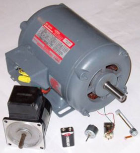
Three
phase AC induction motors rated 1 Hp (746 W) and 25 W with
small motors from CD player, toy and CD/DVD drive reader head
traverse
Where a polyphase electrical supply is available, the three-phase
(or polyphase) AC induction motor is commonly used, especially
for higher-powered motors. The phase differences between the
three phases of the polyphase electrical supply create a rotating
electromagnetic field in the motor.
Through electromagnetic induction, the rotating magnetic field
induces a current in the conductors in the rotor, which in
turn sets up a counterbalancing magnetic field that causes
the rotor to turn in the direction the field is rotating.
The rotor must always rotate slower than the rotating magnetic
field produced by the polyphase electrical supply; otherwise,
no counterbalancing field will be produced in the rotor.
Induction motors are the workhorses of industry and motors
up to about 500 kW (670 horsepower) in output are produced
in highly standardized frame sizes, making them nearly completely
interchangeable between manufacturers (although European and
North American standard dimensions are different). Very large
synchronous motors are capable of tens of thousands of kW
in output, for pipeline compressors and wind-tunnel drives.
There are two types of rotors used in induction motors.
Squirrel
Cage rotors: Most common AC motors use the squirrel cage
rotor, which will be found in virtually all domestic and light
industrial alternating current motors. The squirrel cage takes
its name from its shape - a ring at either end of the rotor,
with bars connecting the rings running the length of the rotor.
It is typically cast aluminum or copper poured between the
iron laminates of the rotor, and usually only the end rings
will be visible. The vast majority of the rotor currents will
flow through the bars rather than the higher-resistance and
usually varnished laminates. Very low voltages at very high
currents are typical in the bars and end rings; high efficiency
motors will often use cast copper in order to reduce the resistance
in the rotor.
In operation, the squirrel cage motor may be viewed as a transformer
with a rotating secondary - when the rotor is not rotating
in sync with the magnetic field, large rotor currents are
induced; the large rotor currents magnetize the rotor and
interact with the stator's magnetic fields to bring the rotor
into synchronization with the stator's field. An unloaded
squirrel cage motor at synchronous speed will only consume
electrical power to maintain rotor speed against friction
and resistance losses; as the mechanical load increases, so
will the electrical load - the electrical load is inherently
related to the mechanical load. This is similar to a transformer,
where the primary's electrical load is related to the secondary's
electrical load.
This is why, as an example, a squirrel cage blower motor may
cause the lights in a home to dim as it starts, but doesn't
dim the lights when its fanbelt (and therefore mechanical
load) is removed. Furthermore, a stalled squirrel cage motor
(overloaded or with a jammed shaft) will consume current limited
only by circuit resistance as it attempts to start. Unless
something else limits the current (or cuts it off completely)
overheating and destruction of the winding insulation is the
likely outcome.
Virtually every washing machine, dishwasher, standalone fan,
record player, etc. uses some variant of a squirrel cage motor.
Wound
Rotor: An alternate design, called the wound rotor, is
used when variable speed is required. In this case, the rotor
has the same number of poles as the stator and the windings
are made of wire, connected to slip rings on the shaft. Carbon
brushes connect the slip rings to an external controller such
as a variable resistor that allows changing the motor's slip
rate. In certain high-power variable speed wound-rotor drives,
the slip-frequency energy is captured, rectified and returned
to the power supply through an inverter.
Compared to squirrel cage rotors, wound rotor motors are expensive
and require maintenance of the slip rings and brushes, but
they were the standard form for variable speed control before
the advent of compact power electronic devices. Transistorized
inverters with variable frequency drive can now be used for
speed control and wound rotor motors are becoming less common.
(Transistorized inverter drives also allow the more-efficient
three-phase motors to be used when only single-phase mains
current is available, but this is never used in house hold
appliances, because it can cause electrical interference and
because of high power requirements.)
Several methods of starting a polyphase motor are used. Where
the large inrush current and high starting torque can be permitted,
the motor can be started across the line, by applying full
line voltage to the terminals. Where it is necessary to limit
the starting inrush current (where the motor is large compared
with the short-circuit capacity of the supply), reduced voltage
starting using either series inductors, an autotransformer,
thyristors, or other devices are used. A technique sometimes
used is star-delta starting, where the motor coils are initially
connected in wye for acceleration of the load, then switched
to delta when the load is up to speed. This technique is more
common in Europe than in North America. Transistorized drives
can directly vary the applied voltage as required by the starting
characteristics of the motor and load.
This type of motor is becoming more common in traction applications
such as locomotives, where it is known as the asynchronous
traction motor.
The speed of the AC motor is determined primarily by the frequency
of the AC supply and the number of poles in the stator winding,
according to the relation:
Ns
= 120F / p
where
Ns = Synchronous speed, in revolutions per minute
F = AC power frequency
p = Number of poles per phase winding
Actual
RPM for an induction motor will be less than this calculated
synchronous speed by an amount known as slip that increases
with the torque produced. With no load the speed will be very
close to synchronous. When loaded, standard motors have between
2-3% slip, special motors may have up to 7% slip, and a class
of motors known as torque motors are rated to operate at 100%
slip (0 RPM/full stall).
The slip of the AC motor is calculated by:
S = (Ns
? Nr) / Ns
where
Nr = Rotational speed, in revolutions per minute.
S = Normalised Slip, 0 to 1.
As an
example, a typical four-pole motor running on 60 Hz might
have a nameplate rating of 1725 RPM at full load, while its
calculated speed is 1800.
The speed in this type of motor has traditionally been altered
by having additional sets of coils or poles in the motor that
can be switched on and off to change the speed of magnetic
field rotation. However, developments in power electronics
mean that the frequency of the power supply can also now be
varied to provide a smoother control of the motor speed.
Three-phase
AC synchronous motors
If connections
to the rotor coils of a three-phase motor are taken out on
slip-rings and fed a separate field current to create a continuous
magnetic field (or if the rotor consists of a permanent magnet),
the result is called a synchronous motor because the rotor
will rotate in synchronism with the rotating magnetic field
produced by the polyphase electrical supply.
The synchronous
motor can also be used as an alternator.
Nowadays,
synchronous motors are frequently driven by transistorized
variable frequency drives. This greatly eases the problem
of starting the massive rotor of a large synchronous motor.
They may also be started as induction motors using a squirrel-cage
winding that shares the common rotor: once the motor reaches
synchronous speed, no current is induced in the squirrel-cage
winding so it has little effect on the synchronous operation
of the motor, aside from stabilizing the motor speed on load
changes.
Synchronous
motors are occasionally used as traction motors; the TGV may
be the best-known example of such use.
Two-phase
AC servo motors
A typical two-phase AC servo motor has a squirrel-cage rotor
and a field consisting of two windings: 1) a constant-voltage
(AC) main winding, and 2) a control-voltage (AC) winding in
quadrature with the main winding so as to produce a rotating
magnetic field. The electrical resistance of the rotor is
made high intentionally so that the speed-torque curve is
fairly linear. Two-phase servo motors are inherently high-speed,
low-torque devices, heavily geared down to drive the load.
Single-phase
AC induction motors
Three-phase
motors inherently produce a rotating magnetic field. However,
when only single-phase power is available, the rotating magnetic
field must be produced using other means. Several methods
are commonly used.
A common
single-phase motor is the shaded-pole motor, which is used
in devices requiring low torque, such as electric fans or
other small household appliances. In this motor, small single-turn
copper "shading coils" create the moving magnetic
field. Part of each pole is encircled by a copper coil or
strap; the induced current in the strap opposes the change
of flux through the coil (Lenz's Law), so that the maximum
field intensity moves across the pole face on each cycle,
thus producing the required rotating magnetic field.
Another
common single-phase AC motor is the split-phase induction
motor, commonly used in major appliances such as washing machines
and clothes dryers. Compared to the shaded pole motor, these
motors can generally provide much greater starting torque
by using a special startup winding in conjunction with a centrifugal
switch.
In the split-phase motor, the startup winding is designed
with a higher resistance than the running winding. This creates
an LR circuit which slightly shifts the phase of the current
in the startup winding. When the motor is starting, the startup
winding is connected to the power source via a set of spring-loaded
contacts pressed upon by the not-yet-rotating centrifugal
switch. The starting winding is wound with fewer turns of
smaller wire than the main winding, so it has a lower inductance
(L) and higher resistance (R). The lower L/R ratio creates
a small phase shift, not more than about 30 degrees, between
the flux due to the main winding and the flux of the starting
winding. The starting direction of rotation may be reversed
simply by exchanging the connections of the startup winding
relative to the running winding.
The phase of the magnetic field in this startup winding is
shifted from the phase of the mains power, allowing the creation
of a moving magnetic field which starts the motor. Once the
motor reaches near design operating speed, the centrifugal
switch activates, opening the contacts and disconnecting the
startup winding from the power source. The motor then operates
solely on the running winding. The starting winding must be
disconnected since it would increase the losses in the motor.
In a capacitor start motor, a starting capacitor is inserted
in series with the startup winding, creating an LC circuit
which is capable of a much greater phase shift (and so, a
much greater starting torque). The capacitor naturally adds
expense to such motors.
Another variation is the Permanent Split-Capacitor (PSC) motor
(also known as a capacitor start and run motor). This motor
operates similarly to the capacitor-start motor described
above, but there is no centrifugal starting switch and the
second winding is permanently connected to the power source.
PSC motors are frequently used in air handlers, fans, and
blowers and other cases where a variable speed is desired.
By changing taps on the running winding but keeping the load
constant, the motor can be made to run at different speeds.
Also provided all 6 winding connections are available separately,
a 3 phase motor can be converted to a capacitor start and
run motor by commoning two of the windings and connecting
the third via a capacitor to act as a start winding.
Repulsion motors are wound-rotor single-phase AC motors that
are similar to universal motors. In a repulsion motor, the
armature brushes are shorted together rather than connected
in series with the field. Several types of repulsion motors
have been manufactured, but the repulsion-start induction-run
(RS-IR) motor has been used most frequently. The RS-IR motor
has a centrifugal switch that shorts all segments of the commutator
so that the motor operates as an induction motor once it has
been accelerated to full speed. RS-IR motors have been used
to provide high starting torque per ampere under conditions
of cold operating temperatures and poor source voltage regulation.
Few repulsion motors of any type are sold as of 2006.
Single-phase
AC synchronous motors
Small
single-phase AC motors can also be designed with magnetized
rotors (or several variations on that idea). The rotors in
these motors do not require any induced current so they do
not slip backward against the mains frequency. Instead, they
rotate synchronously with the mains frequency. Because of
their highly accurate speed, such motors are usually used
to power mechanical clocks, audio turntables, and tape drives;
formerly they were also much used in accurate timing instruments
such as strip-chart recorders or telescope drive mechanisms.
The shaded-pole synchronous motor is one version.
Because inertia makes it difficult to instantly accelerate
the rotor from stopped to synchronous speed, these motors
normally require some sort of special feature to get started.
Various designs use a small induction motor (which may share
the same field coils and rotor as the synchronous motor) or
a very light rotor with a one-way mechanism (to ensure that
the rotor starts in the "forward" direction).
Torque
motors
A torque
motor is a specialized form of induction motor which is capable
of operating indefinitely at stall (with the rotor blocked
from turning) without damage. In this mode, the motor will
apply a steady torque to the load (hence the name). A common
application of a torque motor would be the supply- and take-up
reel motors in a tape drive. In this application, driven from
a low voltage, the characteristics of these motors allow a
relatively-constant light tension to be applied to the tape
whether or not the capstan is feeding tape past the tape heads.
Driven from a higher voltage, (and so delivering a higher
torque), the torque motors can also achieve fast-forward and
rewind operation without requiring any additional mechanics
such as gears or clutches.
Stepper
motors
Closely
related in design to three-phase AC synchronous motors are
stepper motors, where an internal rotor containing permanent
magnets or a large iron core with salient poles is controlled
by a set of external magnets that are switched electronically.
A stepper motor may also be thought of as a cross between
a DC electric motor and a solenoid. As each coil is energized
in turn, the rotor aligns itself with the magnetic field produced
by the energized field winding. Unlike a synchronous motor,
in its application, the motor may not rotate continuously;
instead, it "steps" from one position to the next
as field windings are energized and deenergized in sequence.
Depending on the sequence, the rotor may turn forwards or
backwards.
Simple stepper motor drivers entirely energize or entirely
deenergize the field windings, leading the rotor to "cog"
to a limited number of positions; more sophisticated drivers
can proportionally control the power to the field windings
allowing the rotors to position "between" the "cog"
points and thereby rotate extremely smoothly. Computer controlled
stepper motors are one of the most versatile forms of positioning
systems, particularly when part of a digital servo-controlled
system.
Stepper motors can be rotated to a specific angle with ease,
and hence stepper motors are used in computer disk drives,
where the high precision they offer is necessary for the correct
functioning of, for example, a hard disk drive or CD drive.
Permanent
magnet motor
A permanent
magnet motor is the same as the conventional dc machine except
the fact that the field winding is replaced by permanent magnets.
By doing this, the machine would act like a constant excitation
dc machine (separately excited dc machine).
These
motors usually have a small rating, ranging up to a few horsepower.
They are used in small appliances, battery operated vehicles,
for medical purposes, in other medical equipment such as x-ray
machines. These motors are also used toys, in automobiles
as auxiliary motors for the purposes of seat adjustment, power
windows, mirror adjustment and the like.
Brushless
DC motors
Many of
the limitations of the classic commutator DC motor are due
to the need for brushes to press against the commutator. This
creates friction. At higher speeds, brushes have increasing
difficulty in maintaining contact. Brushes may bounce off
the irregularities in the commutator surface, creating sparks.
This limits the maximum speed of the machine. The current
density per unit area of the brushes limits the output of
the motor. The imperfect electric contact also causes electrical
noise. Brushes eventually wear out and require replacement,
and the commutator itself is subject to wear and maintenance.
The commutator assembly on a large machine is a costly element,
requiring precision assembly of many parts.
These
problems are eliminated in the brushless motor. In this motor,
the mechanical "rotating switch" or commutator/brushgear
assembly is replaced by an external electronic switch synchronised
to the motor's position. Brushless motors are typically 85-90%
efficient whereas DC motors with brushgear are typically 75-80%
efficient.
Midway
between ordinary DC motors and stepper motors lies the realm
of the brushless DC motor. Built in a fashion very similar
to stepper motors, these often use a permanent magnet external
rotor, three phases of driving coils, one or more Hall effect
devices to sense the position of the rotor, and the associated
drive electronics. The coils are activated, one phase after
the other, by the drive electronics as cued by the signals
from the Hall effect sensors. In effect, they act as three-phase
synchronous motors containing their own variable frequency
drive electronics. A specialized class of brushless DC motor
controllers utilize EMF feedback through the main phase connections
instead of Hall effect sensors to determine position and velocity.
These motors are used extensively in electric radio-controlled
vehicles.
Brushless
DC motors are commonly used where precise speed control is
necessary, computer disk drives or in video cassette recorders
the spindles within CD, CD-ROM (etc.) drives, and mechanisms
within office products such as fans, laser printers and photocopiers.
They have several advantages over conventional motors:
- Compared
to AC fans using shaded-pole motors, they are very efficient,
running much cooler than the equivalent AC motors. This
cool operation leads to much-improved life of the fan's
bearings.
- Without
a commutator to wear out, the life of a DC brushless motor
can be significantly longer compared to a DC motor using
brushes and a commutator. Commutation also tends to cause
a great deal of electrical and RF noise; without a commutator
or brushes, a brushless motor may be used in electrically
sensitive devices like audio equipment or computers.
- The
same Hall effect devices that provide the commutation can
also provide a convenient tachometer signal for closed-loop
control (servo-controlled) applications. In fans, the tachometer
signal can be used to derive a
- fan
okay" signal.
- The
motor can be easily synchronized to an internal or external
clock, leading to precise speed control.
- Brushed
motors cannot be used in the vacuum of space because they
will weld themselves into an immovable position.
Modern DC brushless motors range in power from a fraction
of a watt to many kilowatts. Larger brushless motors up
to about 100 kW rating are used in electric vehicles. They
also find significant use in high-performance electric model
aircraft.
Coreless
DC motors
Nothing
in the design of any of the motors described above requires
that the iron (steel) portions of the rotor actually rotate;
torque is only exerted on the windings of the electromagnets.
Taking advantage of this fact is the coreless DC motor, a
specialized form of a brush DC motor. Optimized for rapid
acceleration, these motors have a rotor that is constructed
without any iron core. The rotor can take the form of a winding-filled
cylinder inside the stator magnets, a basket surrounding the
stator magnets, or a flat pancake (possibly formed on a printed
wiring board) running between upper and lower stator magnets.
The windings are typically stabilized by being impregnated
with epoxy resins.
Because the rotor is much lighter in weight (mass) than a
conventional rotor formed from copper windings on steel laminations,
the rotor can accelerate much more rapidly, often achieving
a mechanical time constant under 1 ms. This is especially
true if the windings use aluminum rather than the heavier
copper. But because there is no metal mass in the rotor to
act as a heat sink, even small coreless motors must often
be cooled by forced air.
These motors were commonly used to drive the capstan(s) of
magnetic tape drives and are still widely used in high-performance
servo-controlled systems.
Linear
motors
A linear motor is essentially an electric motor that has been
"unrolled" so that instead of producing a torque
(rotation), it produces a linear force along its length by
setting up a traveling electromagnetic field.
Linear
motors are most commonly induction motors or stepper motors.
You can find a linear motor in a maglev (Transrapid) train,
where the train "flies" over the ground.
Nano
motor
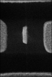 Nanomotor
constructed at UC Berkeley. The motor is about 500nm across:
300 times smaller than the diameter of a human hair Nanomotor
constructed at UC Berkeley. The motor is about 500nm across:
300 times smaller than the diameter of a human hair
Researchers
at University of California, Berkeley, have developed rotational
bearings based upon multiwall carbon nanotubes. By attaching
a gold plate (with dimensions of order 100nm) to the outer
shell of a suspended multiwall carbon nanotube (like nested
carbon
cylinders), they are able to electrostatically rotate the
outer shell relative to the inner core. These bearings are
very robust; Devices have been oscillated thousands of times
with no indication of wear. The work was done in situ in an
SEM. These nanoelectromechanical systems (NEMS) are the next
step in miniaturization that may find their way into commercial
aspects in the future.
Notice: The thin vertical string seen in the middle, is the
nanotube to which the rotor is attached. When the outer tube
is sheared, the rotor is able to spin freely on the nanotube
bearing.
|