|
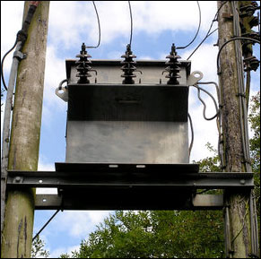 Three-phase
pole-mounted step-down transformer. Three-phase
pole-mounted step-down transformer.
A transformer
is an electrical device that transfers energy from one circuit
to another by magnetic coupling with no moving parts. A transformer
comprises two or more coupled windings, or a single tapped
winding and, in most cases, a magnetic core to concentrate
magnetic flux. An alternating current in one winding creates
a time-varying magnetic flux in the core, which induces a
voltage in the other windings. Transformers are used to convert
between high and low voltages, to change impedance, and to
provide electrical isolation between circuits.
Overview
The transformer
is one of the simplest of electrical devices. Its basic principles
have not changed over the last one hundred years, yet transformer
designs and materials continue to be improved. Transformers
are essential for high voltage power transmission, which makes
long distance transmission economically practical. This advantage
was the principal factor in the selection of alternating current
power transmission in the "War of Currents" in the
late 1880s.
Audio frequency transformers, (at the time called repeating
coils), were used by the earliest experimenters in the development
of the telephone. While some electronics applications of the
transformer have been made obsolete by new technologies, transformers
are still found in many electronic devices.
Transformers
come in a range of sizes from a thumbnail-sized coupling transformer
hidden inside a stage microphone to huge gigawatt units used
to interconnect large portions of national power grids. All
operate with the same basic principles and with many similarities
in their parts.
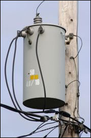 Single
phase pole-mounted step-down transformer Single
phase pole-mounted step-down transformer
Transformers
alone cannot do the following:
| |
- Convert
DC to AC or vice versa
- Change
the voltage or current of DC
- Change
the AC supply frequency.
|
Invention
Those
credited with the invention of the transformer include:
- Michael
Faraday, who invented an 'induction ring' on August 29,
1831. This was the first transformer, although Faraday used
it only to demonstrate the principle of electromagnetic
induction and did not foresee the use to which it would
eventually be put.
- Lucien
Gaulard and John Dixon Gibbs, who first exhibited a device
called a 'secondary generator' in London in 1881 and then
sold the idea to American company Westinghouse. This may
have been the first practical power transformer, but was
not the first transformer of any kind. They also exhibited
the invention in Turin in 1884, where it was adopted for
an electric lighting system. Their early devices used an
open iron core, which was later abandoned in favour of a
more efficient circular core with a closed magnetic path.
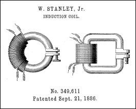
- William
Stanley, an engineer for Westinghouse, who built the first
practical device in 1885 after George Westinghouse bought
Gaulard and Gibbs' patents. The core was made from interlocking
E-shaped iron plates. This design was first used commercially
in 1886.
- Hungarian
engineers Károly Zipernowsky, Ottó Bláthy
and Miksa Déri at the Ganz company in Budapest in
1885, who created the efficient "ZBD" model based
on the design by Gaulard and Gibbs.
- Nikola
Tesla in 1891 invented the Tesla coil, which is a high-voltage,
air-core, dual-tuned resonant transformer for generating
very high voltages at high frequency.
Many others
have patents on transformers
Transformer
designs
Autotransformers

An autotransformer
has only a single winding, which is tapped at some point along
the winding. AC or pulsed voltage is applied across a portion
of the winding, and a higher (or lower) voltage is produced
across another portion of the same winding. While theoretically
separate parts of the winding can be used for input and output,
in practice the higher voltage will be connected to the ends
of the winding, and the lower voltage from one end to a tap.
For example, a transformer with a tap at the center of the
winding can be used with 230 volts across the entire winding,
and 115 volts between one end and the tap. It can be connected
to a 230 volt supply to drive 115 volt equipment, or reversed
to drive 230 volt equipment from 115 volts. As the same winding
is used for input and output, the flux in the core is partially
cancelled, and a smaller core can be used. For voltage ratios
not exceeding about 3:1, an autotransformer is cheaper, lighter,
smaller and more efficient than a true (two-winding) transformer
of the same rating.
In practice,
transformer losses mean that autotransformers are not perfectly
reversible; one designed for stepping down a voltage will
deliver slightly less voltage than required if used to step
up. The difference is usually slight enough to allow reversal
where the actual voltage level is not critical.
By exposing
part of the winding coils and making the secondary connection
through a sliding brush, an autotransformer with a near-continuously
variable turns ratio can be obtained, allowing for very small
increments of voltage.
Polyphase
transformers
For three-phase
power, three separate single-phase transformers can be used,
or all three phases can be connected to a single polyphase
transformer. The three primary windings are connected together
and the three secondary windings are connected together. The
most common connections are Y-?, ?-Y, ?-? and Y-Y. A vector
group indicates the configuration of the windings and the
phase angle difference between them. If a winding is connected
to earth (grounded), the earth connection point is usually
the center point of a Y winding. There are many possible configurations
that may involve more or fewer than six windings and various
tap connections.
The Y-?
transform is a mathematical technique to simplify analysis
of an electrical network.
Resonant
transformers
A resonant transformer is one that operates at the resonant
frequency of one or more of its coils and, usually, an external
capacitor. The resonant coil, usually the secondary, acts
as an inductor, and is connected in series with a capacitor.
If the primary coil is driven by a periodic source of alternating
current, such as a square or Sawtooth wave , each pulse of
current helps to build up an oscillation in the secondary
coil. Due to resonance, a very high voltage can develop across
the secondary, until it is limited by some process such as
electrical breakdown. These devices are therefore used to
generate high alternating voltages. The current available
from this type of coil can be much larger than that from electrostatic
machines such as the Van de Graaff generator and Wimshurst
machine. They also run at a higher operating temperature than
standard units.
Examples:
- Tesla
coil
- Oudin
coil (or Oudin resonator; named after its inventor Paul
Oudin)
- D'Arsonval
apparatus
- Ignition
coil or induction coil used in the ignition system of a
petrol engine
- Flyback
transformer of a CRT television set or video monitor.
- Electrical
breakdown and insulation testing of high voltage equipment
and cables
Other
applications of resonant transformers are as coupling between
stages of a superheterodyne receiver, where the selectivity
of the receiver is provided by the tuned transformers of the
intermediate-frequency amplifiers.
A voltage
regulating transformer uses a resonant winding and allows
part of the core to go into saturation on each cycle of the
alternating current. This effect stabilizes the output of
the regulating transformer, which can be used for equipment
that is sensitive to variations of the supply voltage. Saturating
transformers provide a simple rugged method to stabilize an
ac power supply. However, due to the hysteresis losses accompanying
this type of operation, efficiency is low.
Instrument
transformers
Current
transformers
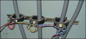
Current
transformers used in metering equipment for three-phase 400
ampere electricity supply
A current
transformer is a type of "instrument transformer"
that is designed to provide a current in its secondary which
is accurately proportional to the current flowing in its primary.
Current
transformers are commonly used in metering and protective
relaying to facilitate the measurement of large currents and
isolation of high voltage systems which would be difficult
to measure more directly.
Current
transformers are often constructed by passing a single primary
turn (either an insulated cable or an uninsulated conductor
(copper or aluminum are typical in electric utility applications)
through a well-insulated toroidal core wrapped with many turns
of wire. Current transformers (CTs) are used extensively in
the electrical power industry for monitoring of the power
grid. The CT is described by its current ratio from primary
to secondary. Common secondaries are 1 or 5 amperes. The secondary
winding can be single ratio or multi ratio, with five taps
being common for multi ratio CTs. Typically, the secondary
connection points are labeled as X1, X2 and so on. The multi
ratio CTs are typically used for current matching in current
differential protective relaying applications. Often, multiple
CTs will be installed as a "stack" for various uses
(for example, protection devices and revenue metering may
use separate CTs). For a three-stacked CT application, the
secondary winding connection points are typically labeled
Xn, Yn, Zn.
Specially
constructed "wideband current transformers" are
also used (usually with an oscilloscope) to measure waveforms
of high frequency or pulsed currents. One type of specially
constructed wideband transformer provides a voltage output
that is proportional to the measured current. Another type
(called a Rogowski coil) requires an external integrator in
order to provide a voltage output that is proportional to
the measured current.
Care must
be taken that the secondary of a current transformer is not
disconnected from its load while current is flowing in the
primary, as this will produce a dangerously high voltage across
the open secondary.
Voltage
transformers
Voltage
transformers (also called potential transformers) are another
type of instrument transformer, used for metering and protection
in high-voltage circuits. They are designed to present negligible
load to the voltage being measured and to have a precise voltage
ratio to accurately step down high voltages so that metering
and protective relay equipment can be operated at a lower
potential. Typically the secondary of a voltage transformer
is rated for 69 or 120 Volts at rated primary voltage, to
match the input ratings of protection relays.
The transformer
winding high-voltage connection points are typically labelled
as H1, H2 (sometimes H0 if it is internally grounded) and
X1, X2, and sometimes an X3 tap may be present. Sometimes
a second isolated winding (Y1, Y2, Y3) may also be available
on the same voltage transformer. The high side (primary) may
be connected phase to ground or phase to phase. The low side
(secondary) is usually phase to ground.
The terminal
identifications (H1, X1, Y1, etc.) are often referred to as
polarity. This applies to current transformers as well. At
any instant terminals with the same suffix numeral have the
same polarity and phase. Correct identification of terminals
and wiring is important for proper operation of metering and
protection relays.
Pulse
transformers
A pulse
transformer is a transformer that is optimised for transmitting
rectangular electrical pulses (that is, pulses with fast rise
and fall times and a constant amplitude). Small versions called
signal types are used in digital logic and telecommunications
circuits, often for matching logic drivers to transmission
lines. Medium-sized power versions are used in power-control
circuits such as camera flash controllers. Larger power versions
are used in the electrical power distribution industry to
interface low-voltage control circuitry to the high-voltage
gates of power semiconductors such as TRIACs, IGBTs, thyristors
and MOSFETs. Special high voltage pulse transformers are also
used to generate high power pulses for radar, particle accelerators,
or other pulsed power applications.
To minimise
distortion of the pulse shape, a pulse transformer needs to
have low values of leakage inductance and distributed capacitance,
and a high open-circuit inductance. In power-type pulse transformers,
a low coupling capacitance (between the primary and secondary)
is important to protect the circuitry on the primary side
from high-powered transients created by the load. For the
same reason, high insulation resistance and high breakdown
voltage are required. A good transient response is necessary
to maintain the rectangular pulse shape at the secondary,
because a pulse with slow edges would create switching losses
in the power semiconductors.
The product of the peak pulse voltage and the duration of
the pulse (or more accurately, the voltage-time integral)
is often used to characterise pulse transformers. Generally
speaking, the larger this product, the larger and more expensive
the transformer.
RF
transformers (transmission line transformers)

Coils
with tickler.
For radio frequency use, transformers are sometimes made from
configurations of transmission line, sometimes bifilar or
coaxial cable, wound around ferrite or other types of core.
This style of transformer gives an extremely wide bandwidth
but only a limited number of ratios (such as 1:9, 1:4 or 1:2)
can be achieved with this technique.
The core material increases the inductance dramatically, thereby
raising its Q factor. The cores of such transformers help
improve performance at the lower frequency end of the band.
Older style RF transformers sometimes used a third coil (called
a tickler winding) to inject feedback into an earlier (detector)
stage in antique regenerative radio receivers.
Baluns
Baluns
are transformers designed specifially to connect between balanced
and unbalanced circuits. These are sometimes made from configurations
of transmission line and sometimes bifilar or coaxial cable
and are similar to transmission line transformers in constructuion
and operation. This style of transformer is frequently used
as an impedance matching balun to convert from 300 ohm balanced
to 75 ohm unbalanced in FM receivers.
Audio
transformers
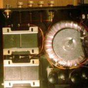 Transformers
in a tube amplifier. Output transformers are on the left.
The power supply toroidal transformer is on right. Transformers
in a tube amplifier. Output transformers are on the left.
The power supply toroidal transformer is on right.
Transformers
are used in valve (vacuum tube) audio circuits to match the
high impedance of the valve to the lower impedance of the
load. This is no longer necessary with transistor circuits,
which can always be made with a lower output impedance than
that of the load, and so these circuits use impedance bridging
instead. [1]
Audio
transformers are usually the factor which limit sound quality;
electronic circuits with wide frequency response and low distortion
are relatively simple to design.
Transformers
are also used in DI boxes to convert impedance from high-impedance
instruments (for example, bass guitars) to enable them to
be connected to a microphone input on the mixing console.
Output
transformers
A particularly
critical component is the output transformer of an audio power
amplifier. Valve circuits for quality reproduction have long
been produced with no other (inter-stage) audio transformers,
but an output transformer is needed to couple the relatively
high impedance (up to a few hundred ohms depending upon configutation)
of the output valve(s) to the low impedance of a loudspeaker.
(The valves can deliver a low current at a high voltage; the
speakers require high current at low voltage.)
For good low-frequency response a relatively large iron core
is required; high power handling increases the required core
size. Low distortion requires iron of adequate properties;
special cores with oriented magnetic domains are used for
best results. Good high-frequency response requires carefully
designed and implemented windings without excessive leakage
inductance or stray capacitance. All this makes for an expensive
component.
Output transformerless audio power valve amplifiers are possible
(e.g., a design by Julius Futterman), but were rarely used
due to other disadvantages.
Early transistor audio power amplifiers often had output transformers,
but they were eliminated as designers discovered how to design
amplifiers without them.
Speaker
transformers
In the same way that transformers are used to create high
voltage power transmission circuits that minimize transmission
losses, speaker transformers allow many individual loudspeakers
to be powered from a single audio circuit operated at higher-than
normal speaker voltages. This application is common in public
address (e.g., Tannoy) applications. Such circuits are commonly
referred to as constant voltage or 70 volt speaker circuits
although the audio waveform is obviously a constantly changing
voltage.
At the audio amplifier, a large audio transformer may be used
to step-up the low impedance, low-voltage output of the amplifier
to the designed line voltage of the speaker circuit. (For
high-powered amps, the amplifier transformer may not be needed.)
Then, a smaller transformer at each speaker returns the voltage
and impedance to ordinary speaker levels. The speaker transformers
commonly have multiple primary taps, allowing the volume at
each speaker to be adjusted in a number of discrete steps.
Use of a constant-voltage speaker circuit means that there
is no need to worry about the impedance presented to the amplifier
output (which would clearly be too low if all of the speakers
were arranged in parallel and would be too complex a design
problem if the speakers were arranged in series-parallel).
The use of higher transmission voltage and impedance means
that power lost in the connecting wire is minimized, even
with the use of small-gauge conductors (and leads to the term
constant voltage as the line voltage doesn't change much as
additional speakers are added to the system). Also, the ability
to adjust, locally, the volume of each speaker (without the
complexity and power loss of an L pad) is a useful feature.
Uses of transformers
- For
supplying power from an alternating current power grid to
equipment which uses a different voltage. May be followed
by a rectification circuit, if direct rather than alternating
power is needed.
-
Adaptation of electrical equipment to supply voltages
for which it was not made. For example, to use U.S.
equipment, designed for 117 V AC, in European countries
with 230 V AC. A transformer or autotransformer may
be used, or electronic voltage changers which do not
use transformers.
-
Use inside solid-state equipment which requires low
voltages to reduce the main electricity voltage to the
required value.
-
Use as an external adapter to power low-voltage solid-state
equipment from higher-voltage main electricity.
- Electric
power transmission over long distances.
- High-voltage
direct-current HVDC power transmission systems
- Large,
specially constructed power transformers are used for electric
arc furnaces used in steelmaking.
- Rotating
transformers are designed so that one winding turns while
the other remains stationary. A common use was the video
head system as used in VHS and Beta video tape players.
These can pass power or radio signals from a stationary
mounting to a rotating mechanism, or radar antenna.
- Sliding
transformers can pass power or signals from a stationary
mounting to a moving part such as a machine tool head. See
linear variable differential transformer.
- Some
rotary transformers are used to couple signals between two
parts which rotate in relation to each other.
- Other
rotary transformers are precisely constructed in order to
measure distances or angles. Usually they have a single
primary and two or more secondaries, and electronic circuits
measure the different amplitudes of the currents in the
secondaries. See synchro and resolver.
- Small
transformers are often used internally to isolate and link
different parts of radio receivers and audio amplifiers,
converting high current low voltage circuits to low current
high voltage, or vice versa.They are usually tuneable, and
labelled filter/bandpass, though technically being transformers/operating
on the same electromagnetic principes. See electronics and
impedance matching. See also isolation transformer and repeating
coil.
- Transformers
may be used as external accessories for impedance matching;
for example to match a microphone to an amplifier. These
were frequently required with valve equipment, but solid-state
electronics are more capable of matching a wide range of
impedances without the need for a transformer.
- Balanced-to-unbalanced
conversion. A special type of transformer called a balun
is used in radio and audio circuits to convert between balanced
circuits and unbalanced transmission lines such as antenna
downleads. A balanced line is one in which the two conductors
(signal and return) have the same impedance to ground: twisted
pair and "balanced twin" are examples. Unbalanced
lines include coaxial cables and strip-line traces on printed
circuit boards. A similar use is for connecting the "single
ended" input stages of an amplifier to the high-powered
"push-pull" output stage.
- Safety.
Transformers are used in home electronics, such as computers,
to decouple them from the power grid that they are connected
to. This is called Galvanic isolation.
|