| |
| Engineering
>> Transformer >> Understanding Transformers |
| |
| Characteristics
and Limitations |
|
| It
is easy to take transformers for granted, because they have
been with us since the early days of electricity. Perhaps their
familiarity has rendered them less glamorous in comparison to
more recently developed electronic and optical components and
technologies. Nevertheless, transformers are a basic electrical
component that we use often. Their ability to transform voltages,
currents, and therefore impedances provide essential tools for
the circuit designer. Here, we review how they work, and discuss
a few of their more prominent limitations and characteristics.
Similar issues apply to ferrite based magnetic components as
well. |
|
| Conceptually,
the transformer is a simple and elegant component resulting
from the interaction of several of Maxwell's equations. Figure
1 shows an idealized transformer. Two sets of windings-call
them #1 and #2, or input and output, or primary and secondary-are
wound around a common magnetic core. If an AC voltage is imposed
on one winding, resulting in current flow, Ampere's law tells
us that magnetic flux will be generated. Because the core is
magnetic, that is, possesses a permeability significantly greater
than that of air or free space, virtually all of the flux stays
in the core rather than spreading out, and is therefore linked
through the turns of the second winding. Faraday's law tells
us that the second winding will exhibit an output voltage determined
by the rate of change of the magnetic flux passing through each
turn of the secondary, multiplied by the number of turns (Figure
2). |
|
|
|
|
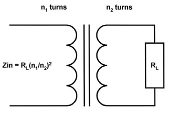
| Figure
1: A transformer is made from a pair of windings around a common
core. It is modeled as a two-port circuit component. |
| |
|
|
|
| Figure
2: The ratio of the number of turns in the windings determines
the voltage and current ratios present in the windings. They
go in opposite directions-if voltage is stepped up, current
is stepped down, and vice-versa. |
| |
| An
ideal transformer will isolate the input circuit from the output
circuit, transform the input voltage by the ratio of the number
of turns in the windings, and be frequency independent. If the
secondary has more turns than the primary, the voltage will
be "stepped up"; if the secondary has fewer turns
than the primary, the voltage will be "stepped down."
The current will change in an inverse fashion. That is, if voltage
is stepped up across a transformer, the current will be decreased
by the same proportion. This is as it must be to conserve energy.
The power that comes out of a transformer must equal the power
that is put into it, less any losses due to such factors as
magnetic imperfections and resistive heating of the transformer
windings. |
|
Practical
Limitations
The idealized transformer described above has only the transformation
property-it doesn't have any losses, or power limitations. Its
frequency response seems to be infinite. Real components have
limited efficiency and bandwidth, and can act in a non-linear
fashion. A circuit model incorporating these imperfections is
shown in Figure 3. The imperfections are shown as equivalent
components added to an ideal transformer. |
|
|
|
|
| Figure
3: Physical effects cause transformers to deviate from the simple
idealized model. Shown is a small signal model which includes
the effects of shunt and inter-winding capacitance, stray inductance,
magnetic loss, and winding resistance. Note that under low frequency
or large-signal conditions, the shunt primary inductance can
become nonlinear if the transformer is driven into saturation. |
|
| These
imperfections are caused by the physical effects listed below.
Also indicated are the components to which they correspond in
the circuit model of Figure 3. |
|
- Nonzero
resistance of the windings (Rp and Rs)
- Frequency
dependence of the material permeability
- Magnetic
losses (Re)
- Intra-winding
capacitance (turn to turn within a winding-Cp)
- Inter-winding
capacitance (primary to secondary-Cps)
- Finite
primary winding inductance (Le)
- Finite
flux capability of the core material, leading to saturation
(non-linear behavior of Le)
- Leakage
inductance of the windings (Lp and Ls)
|
| Let's
review how these factors affect a transformer's operating characteristics.
We'll take a quick overview, and then look at the effects due
to saturation and winding resistance in more detail. |
|
- The
resistance of the windings affects two important characteristics:
power dissipation through heating, and impedance transformation
(or equivalently, resistive voltage drop).
- Magnetic
losses are of two main types. First, if the magnetic core
is electrically conductive-e.g. an iron core-circulating
electrical eddy currents induced by the magnetic fields
will result in waste heating of the transformer core. Second,
if the permeability of the core material is complex at the
frequencies of interest, power will also be dissipated.
The first effect is more important with low frequency power
transformers (and is one reason that they are composed of
laminated sections rather than monolithic bulk material),
while the second occurs with ferrite materials. Both of
these result in power loss through heating of the transformer
core.
- Parasitic
capacitances limit the upper bandwidth of operation and
also reduce the isolation the transformer can provide.
- The
inductance of the primary winding limits the low frequency
operation of the transformer. There are two effects. For
small signal operation, the core will not be saturated,
but the transformer's performance will be limited by the
low winding impedance. For large signal operation, the core
will saturate, and the inductance will change during the
course of a voltage cycle. This causes non-linear behavior,
and can lead to catastrophic transformer failure.
|
| Now,
let's examine the problem of core saturation in more detail. |
|
Of
Transformers and Beads
Power transformers and small signal ferrite inductors (beads,
sleeves, and toroids) are both magnetic devices, although their
applications are at opposite ends of the frequency and power
spectrum. Power transformers and autotransformers are used in
the laboratory to vary mains voltages to the levels required
by different product types and regulatory jurisdictions, and
to check product operation over specified variations. Ferrite
beads, and their multi-turn cousins, common-mode and differential-mode
chokes, are used to present frequency-selective barriers to
unwanted high frequency signals ranging from approximately 100
kHz (for conducted emissions) to frequencies of several hundred
MHz (for radiated emissions). Power transformers are large,
and ferrite beads are relatively small, but both are affected
by primary inductance limitations. |
|
| The
operation of both types of devices is dramatically impaired
when magnetic saturation of their cores occurs. Saturation lowers
the incremental permeability (i.e., the change in flux, B, for
an additional change in magnetizing force, H) of magnetic materials.
Ferrite components for RF suppression applications are usually
intended for use under small signal conditions. Transformers
are inherently large signal devices. For both to operate as
intended, it is essential to understand their magnetic limitations. |
|
| The
key to understanding the operation of magnetic devices is the
relationship between the current that is applied (I, in amperes),
the resulting magnetic field (H, in amperes/meter), and the
resulting magnetic flux (B, in tesla or webers/sq. meter). These
in turn, determine the circuit parameters we usually work with,
such as inductance and impedance. |
|
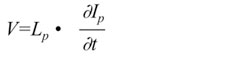
| Inductance
(L) is defined as the instantaneous (or incremental) ratio of
total magnetic flux linkage to applied current. The magnetic
flux linkage is the flux in the magnetic core multiplied by
the number of turns of wire that it passes through. This allows
us to summarize a component's characteristics in the familiar
circuit relation, V= L*di/dt. The inductance varies with the
geometry of the core (mainly the cross-sectional area), the
square of the number of turns, and varies in proportion to the
permeability. |
|
Operating
on the B-H Curve
For an isotropic magnetic material at low frequencies, the relationship
between B and H, or permeability, is scalar. (At higher frequencies
it becomes complex. The imaginary component shows up as a resistive
loss, rather than contributing to inductance). However, the
permeability in a magnetic material is not constant- the magnetic
flux density B increases more and more slowly with increases
in the applied magnetic field. That is, it saturates as a greater
percentage of the internal magnetic domains are aligned with
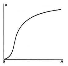
the applied field. This may be written with the formula: |
|
| B=
µ (H) . H |
| |
| A
typical B-H curve is shown in Figure 4. The slope of the curve
decreases with increasing applied field. This means that the
incremental, small signal permeability, and hence the primary
winding inductance, decreases under large signal conditions.
Since the inductance, as noted above, is proportional to the
slope of the B-H curve, the inductance is not constant, but
is instead a decreasing function of the current through the
inductor. The magnetic inductor is only linear under small signal
conditions. |
|
 |
|
| Figure
4: A B-H curve for a magnetic material (hysteresis is ignored).
The inductance is proportional to the derivative, or slope,
of the B-H curve. When the material becomes fully magnetized,
increasing the applied magnetic H-field has little effect on
the resulting flux (B-field) in the material. The slope, and
the inductance, approaches zero. |
| |
Circuit
Effects of Saturation
When power transformers saturate, their operation deteriorates
in dramatic fashion. As Figure 5 shows, a simplified model for
a power transformer consists of an ideal transformer, an allowance
for the resistance of the windings, and a shunt primary inductance.
Power transformers are inherently large signal, low frequency
devices. Operation involves traversing along the B-H curve from
one side to the other as the current and magnetizing H-field
vary simultaneously. |
| |
|
|
|
| Figure
5: Simplified equivalent circuit for a power transformer. When
the core saturates, the primary inductance Lp drops to a very
low value. Large currents flow through the primary winding,
limited mostly by the winding resistance Rp. The secondary voltage
Vout drops dramatically because of the decrease of the ratio
of the rate of change of the linked flux to that of the input
current. |
|
| As
long as the core is not saturated and the primary inductance
is large, everything works fine. But what happens when this
is no longer the case? The relation for the current through
the primary inductance is: |
|
 |
|
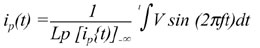
| We
can integrate this to look at the current, noting explicitly
that Lp is also a function of the instantaneous current, i,
and that the applied voltage is sinusoidal: |
|
 |
|
| If
the current becomes large enough to saturate the core, the permeability
drops to a very low value, and therefore, so does the inductance
Lp of the transformer's primary. At this point, several things
happen: |
|
- Very
large currents flow
- The
primary current, and the secondary voltage, become far from
sinusoidal. The primary current gets very large for the
balance of the half-cycle, and the secondary voltage drops
from its initial sinusoidal shape to near zero.
- The
transformer gets hot in a hurry, and consequences such as
blown breakers and inoperative equipment usually follow.
|
| It
is important to realize that the saturation problem is a function
of the applied voltage and frequency only. It is NOT caused
by the amount of current drawn from the secondary winding. |
|
| If
you are working with equipment destined for both the U. S. and
international markets, you will need to generate and transform
both 50 and 60 Hz power. A 50 Hz transformer will easily operate
at 60 Hz, but it doesn't always work the other way around. I
was surprised to find that many transformers and autotransformers
("variacs") sold in the United States are designed
for use at 60 Hertz only. This means that you shouldn't be surprised
if they act badly when you connect them to a 50 Hertz generator
or solid state power source. You can use 60 Hertz transformers
and variacs at 50 Hertz if you derate them by putting less voltage
(about 20% less) across the primary, because then the current
and internal H-fields build up to the saturation level more
slowly. Of course, for a lot of testing you won't be derating
them-you'll want them to operate at a higher than normal (e.g.,
for ITE, you would run at nominal +10% during a safety qualification
test). You have to be careful - while some transformers are
rated for 50/60 Hz operation, others are only rated for 60 Hz.
|
|
| You
can always check that you are in the range of healthy operation
by placing a current clamp over the transformer primary and
monitoring the current flow. If it is sinusoidal, saturation
isn't occurring. As you lower the operating frequency below,
or, alternatively, increase the primary voltage above, the stated
operating parameters of the transformer, the primary current
will develop a large hump as it saturates with each half cycle
of the applied current. This current hump winds up dissipating
in the winding resistance of the primary. Often, circuit breakers
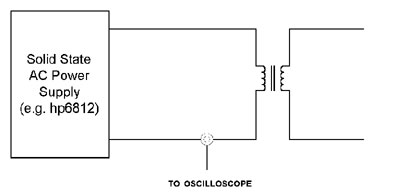
will pop. If a solid state AC source is available, you can easily
check the extremes of useful voltage and frequency operation
for your power transformers (see Figure 6). |
|
 |
|
| Figure
6: You can check the actual extremes of voltage and frequency
over which a transformer will operate with a solid state power
source and a monitoring current clamp. Saturation of the core
will cause large non-sinusoidal currents to flow. |
|
| We
also note that saturation of a ferrite device will reduce its
impedance. Typically this occurs because net DC current is applied
rather than because of low-frequency AC operation. This can
significantly reduce the ferrite's effectiveness as a high frequency
suppression or coupling device (depending on whether it is a
single bead, a common mode choke, or a high frequency signal
transformer). The results will be less spectacular (no smoke)
than for a power transformer because of the lower power involved. |
| |
| Impedance
Transformation Properties of Transformers |
| Another
important characteristic of transformers is the way they transform
impedances, and the deviation from ideal transformation that
can be caused by winding (and wiring) resistance. |
|
| Consider
an ideal transformer with winding 1 connected to an AC voltage
source of value V1 and winding 2 connected to a resistive load
of value R. The transformer has a turns ratio a= (n2/n1). Clearly,
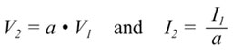
the voltage V2 across the resistor and the current I2 passing
through it must be related to the input voltage and current
by the turns ratio of the transformer. That is, |
|
 |
|
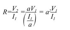
But
we know by Ohm's Law that, for the resistor, V2/I2=R.
If we substitute the above relations into this equation and
solve for V1/I1, we will get the impedance looking "into"
the transformer from side 1. We find that |
|
 |
|
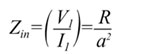
| which
means that |
|
 |
|
| Thus,
a transformer transforms impedance by the square of the turns
ratio. The higher impedance is seen on the side with the greater
number of turns-the high voltage, low current side. Using our
notation, if a>1, we are stepping up the source voltage,
and the impedance seen at winding 1 of the transformer is lower
than that of the load resistance across winding 2. If a<1,
we are stepping down the source voltage, but the input impedance
seen looking into winding 1 is higher than that of the load
resistance. (See Figure 7) |
|
 |
|
| Figure
7: A transformer transforms impedance as the square of the turns
ratio because the voltage and current transformation ratios
work in opposite directions. |
|
| We
now give two examples of how impedance transformation and wiring/winding
resistances interact. Our first example is large-signal - power
distribution, while our second is drawn from small signal audio/telecom
circuitry. |
|
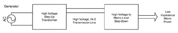
Impedance
Transformation and Power Distribution
The ability to transform voltages and impedances is one of the
reasons that the AC voltage distribution system championed by
Tesla and others won out over Edison's original DC system. In
order to send electric power over long distances with useful
efficiency, it is necessary to minimize the losses due to heating
the power lines. That means that you want to transform the impedance
of the load to a very high value over the transmission path,
so the resistance of the transmission wires is a small fraction
of the resistance of the total circuit. That's why we use high
voltage transmission lines to carry power long distances and
transform it locally to lower levels. (Figure 8). With AC power
distribution, it is easy to change voltages with transformers
as needed to minimize transmission loss. |
|
 |
|
| Figure
8: Power transmission systems use high voltages and high impedances.
This increases efficiency by minimizing the voltage drop across
the transmission wires because the load is transformed up to
a high impedance. |
| |
Resistance
and Impedance Matching Calculations
In small signal applications, such as in an audio or modem interface
circuit, load matching, and hence the proper calculation of
the impedance seen across a coupling transformer are important.
Here, let's use a midband model which assumes that the main
imperfection in the transformer is the resistance of both windings
(Figure 9). Let's further assume that we are interested in creating
an impedance which, seen from the load side, matches that of
the load. This might be important in some telecommunications
applications where a high return loss-that is, a good match
to the line impedance-is desired to meet a performance or regulatory
goal. |
|
 |
|
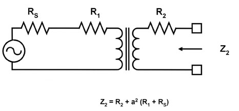
| Figure
9: In matching low level impedances, transformer winding resistance
is significant. This figure shows the transformation viewed
from the output side. |
| |
| The
transformer still transforms impedances with the square of the
turns ratio, but we must account for the resistance of the windings.
Let's assume that the turns ratio is still given by a = (n2/n1)
The impedance seen from the load side (winding 2) becomes: |
|
| Z2
= a2 o (R1+Rs)+R2 |
|
| As
an example, if we had a 1:1 signal transformer with winding
resistances R1 and R2 both equal to 100 ohms, we would have
to set the source resistance Rs to 400 ohms. This seems straightforward
enough, but note that the impedance seen looking into winding
1 is 800 ohms (the transformation of the 600 ohm load and the
effect of the windings). Thus, looking at it from the primary
side, we have a 400 ohm source driving an 800 ohm transformed
load. This is unimportant, because the impedance that matters
for low return loss is that seen looking into winding 2 from
the load (or network) side. Here, we see a matched composite
source (including the transformer) of 600 ohms driving our 600
ohm load. |
|
|
|
|
Figure
10: A completed example where it is desired to select a source
impedance which will cause a 1:1 transformer with 100 ohms resistance
in each winding to present a 600 ohm matched termination to
the telephone network. (a) If the driving voltage source (typically
and op amp) impedance is set to 400 ohms, the desired impedance
is seen looking in from the network side.
(b) The network impedance presented at the input of the transformer,
however, is 800 ohms. This alters the canceling gain required
of a hybrid relative to the situation of zero winding resistance. |
|
Summing
Up
Transformers are indispensable in power distribution as well
as many circuit applications. Knowledge of how they work makes
it easy to understand how to specify and use them effectively
in circuit and laboratory applications. |
|
|
|
|
transformers, current
transformers, potential transformers, voltage transformers, motors,
ac motors, dc motors, 2 stroke engines, two stroke engines, diesel
engines, turbochargers, steam engines, rocket engines, manual transmissions,
horsepower, gas turbine engines, fuel injection systems, car engines,
car cooling systems
|